Mechanical interlock
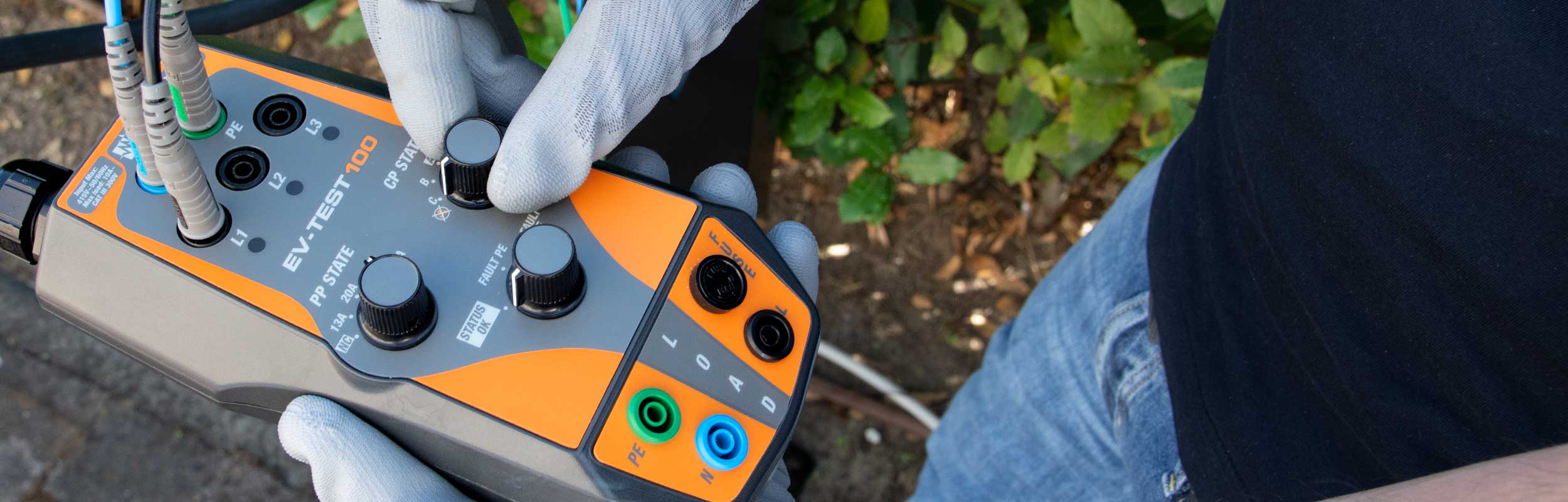
Thanks to the simulation of the vehicle’s status it is possible to verify that, starting from status B, the recharging column blocks the cable’s release.*
* Only for charging stations equipped with an interlock system
| Use for EVSE charging stations | Charging modes 2 and 3 |
| Test cable with connector | Type 2 (IEC 62196-2) |
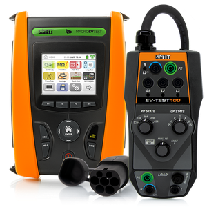
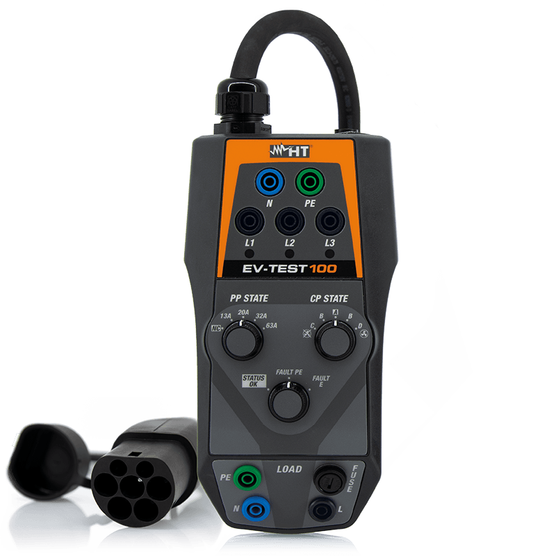
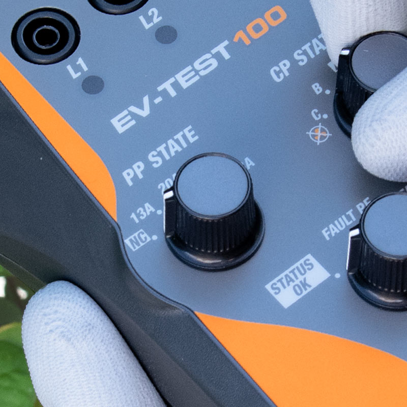
| Vehicle simulation via Control Pilot (CP state) | States A, B, C, D |
| Simulating the current capacity of Proximity Pilot (PP state) | NC, 13A, 30A, 32A, 63A |
| Fault condition simulation on PE | FAULT PE |
| Diode simulation in short circuit | FAULT E |
| EVSE internal counter efficiency check | LOAD |
| Input voltage | Max 415V AC, Phase-Phase, 50 / 60Hz |
| External load L-N-PE | 240V 50/60Hz, Max 10A AC |
| CP signal | PWM 12V |
| External load protection | Fuse FF 10A / 250V, 5x20mm |
| Operating temperature | 0°C ÷ 40°C |
| Operating humidity | <80&RH |

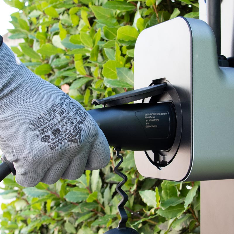
Thanks to the simulation of the vehicle’s status it is possible to verify that, starting from status B, the recharging column blocks the cable’s release.*
* Only for charging stations equipped with an interlock system
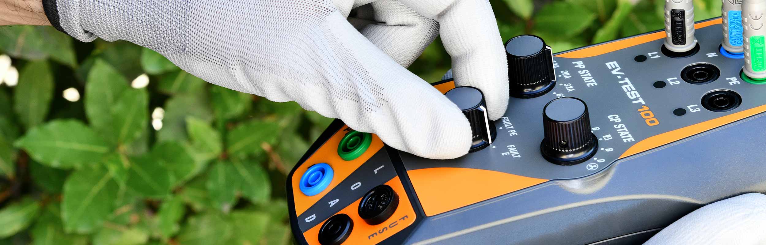
Through the knob it is possible to carry out in a sequence the simulation of the interruption of the protective conductor (Fault PE) and the simulation of an error on the CP signal (Fault E).
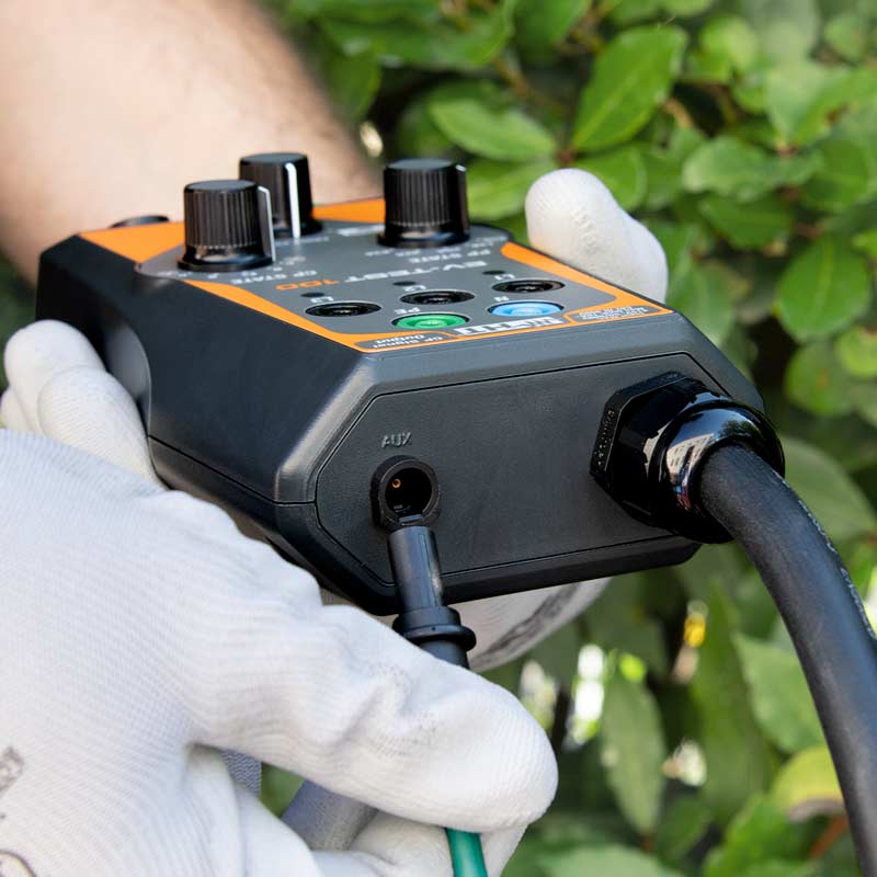
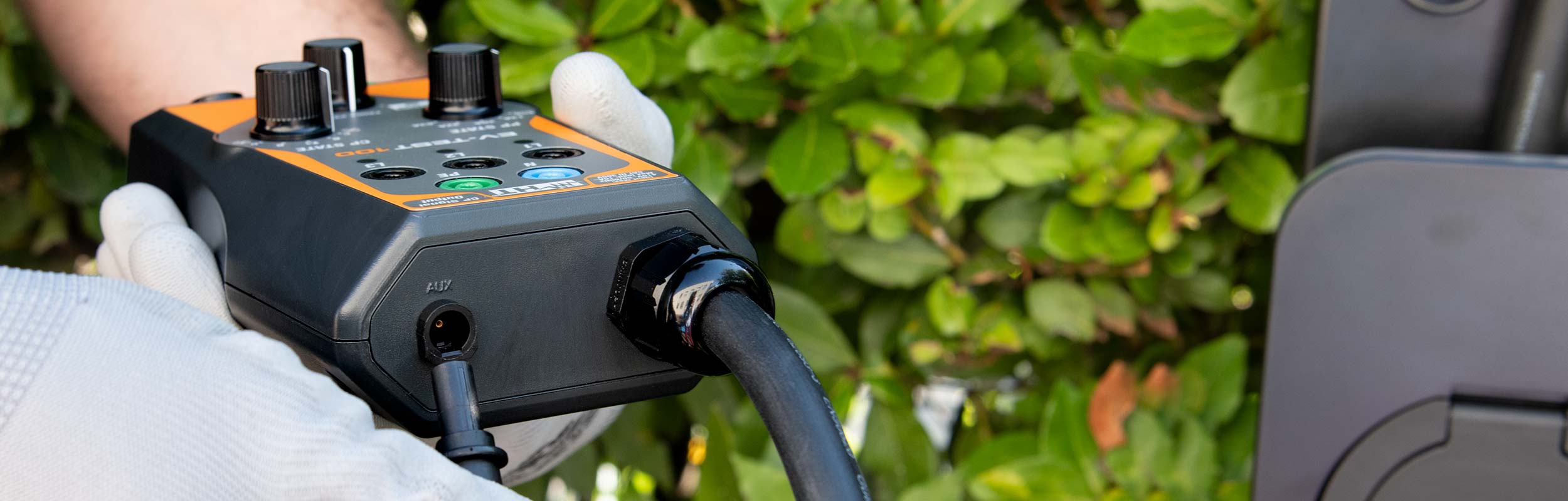
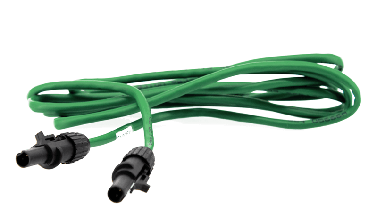
Through the dedicated output and the provided C100EV cable it is possible to verify the recharging mode and the encoding of the recharging current through the acquisition of the PWM signal (pulse width modulation).
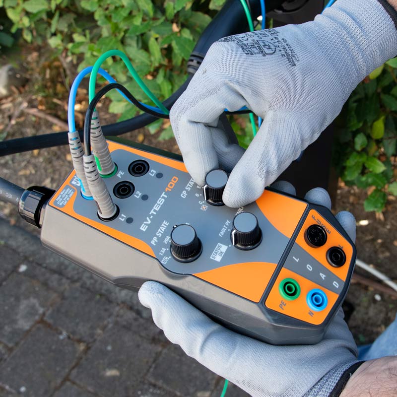
Through PP knob, rated currents of charging cables can be simulated, up to 63A.
Possibility of simulating the various current capacitances of the recharging cable, up to 63A, when EV-TEST 100 is connected to the recharging station.*
* Only for charging stations supporting this function